ALERT
ALERT ATTENTION ⚠️
In observance of a holiday, Agilent CrossLab/iLab Operations Software Support Help Desk will be closed during U.S. hours on Friday, July 3rd, 2026. We will resume regular U.S. support hours on Monday, July 6th, 2026. EU and APAC Support will remain open during this time. For urgent matters, please add "Urgent" to the ticket/email subject or press "1" when prompted to escalate a call on the iLab Support phone, and we will prioritize those requests first.
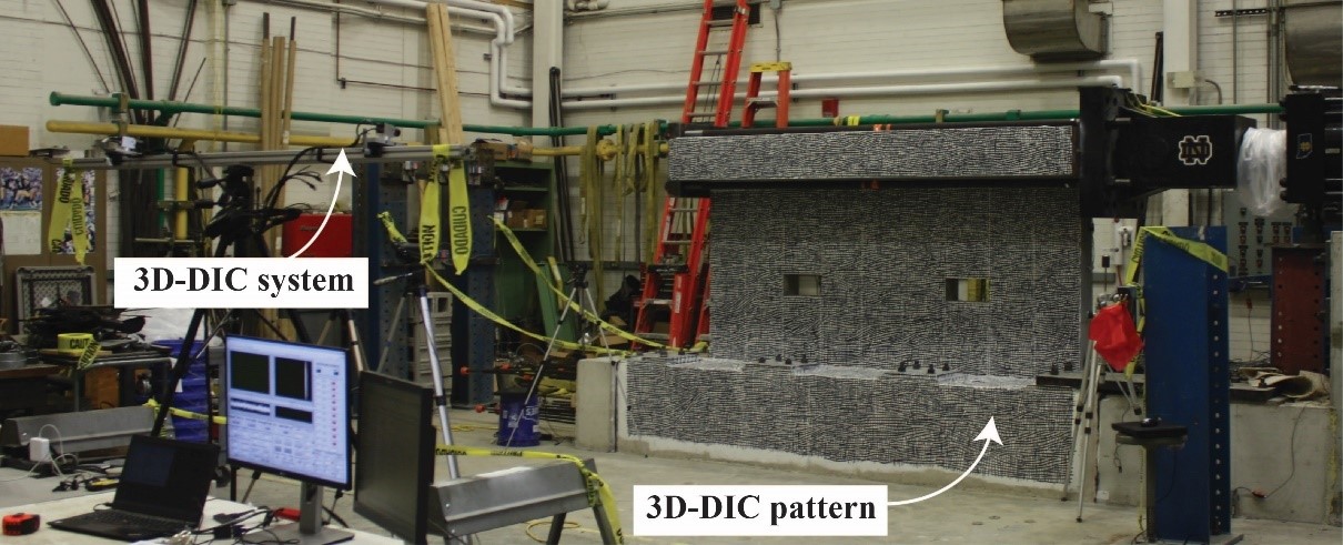
3D-DIC is a non-contact, optical monitoring technique for full-field shape, displacement (movement), and strain measurement on components and structures made from almost any material (concrete, metals, wood, polymers, composites, ceramics, foam, rubber, bone, etc.). During a test, the specimen is photographed with high-resolution digital cameras before and under load (or other excitation). As the specimen moves and deforms, analysis software tracks its distortions in 3D from minute pattern shifts between images such that a full-field of deformations is measured using image correlation and photogrammetric location principles Different from a 2D system, 3D-DIC uses a stereo pair of cameras. 3D-DIC is more practical and more useful than other optical monitoring methods because it can operate on any traceable pattern on a digital image (e.g., spray-on patterns, specimen’s own features, cells, internal micro-structures). Accuracy and precision are related to the size of the field-of-view (FOV) of the monitored specimen and other factors such as the resolution of the captured images, camera calibration, angle between the cameras, and redundancy in the appearance of patterns between multiple images.
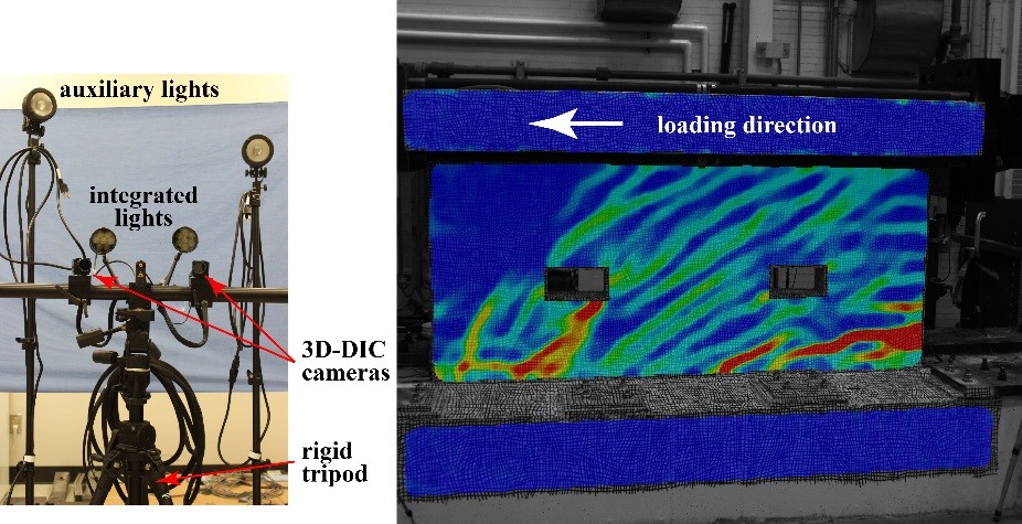
The University of Notre Dame possesses two ARAMIS 3D-DIC systems. These systems can measure surface deformations with an accuracy up to 1/30000 of the field of view and strains with an accuracy up to 0.01%. The 3D-DIC systems (provided by Trilion Quality Systems) consist of two pairs of cameras (i.e., two 3D-DIC sensors): 1) one 5 Megapixel camera pair capable of capturing images at 7 frames/second at full resolution of 2448 x 2050 pixels; and 2) one high speed camera pair capable of capturing images at 510 frames/second at full resolution of 1280 x 1024 pixels, 1250 frames/second at a resolution of 800 x 600 pixels, or 5000 frames/second at a resolution of 376 x 274 pixels. The camera pairs can be used together or separately. They are mounted on heavy-duty tripods with pan-tilt heads and both short and long camera bars. Each pair of cameras is outfitted with wide angle and close-up lenses. The equipment also includes an 8 channel data logger with sensor controller and an image processing laptop. Calibration objects range from 0.984 in. panels to 3.28 ft and 6.56 ft crosses, enabling FOVs up to 16.4 ft.
(a)
(b) (c)
Fig. 1. 3D-DIC: (a) reinforced concrete wall specimen with 3D-DIC pattern; (b) one system with 2 cameras acting as a pair; (b) measured maximum principal strain field showing crack pattern on front surface of wall
| Yahya (Gino) Kurama, PhD, PE | Director | (574) 386-4911 | ykurama@nd.edu |
| Ashley Thrall, PhD | Co-Director |
| Name | Role | Phone | Location | |
|---|---|---|---|---|
| Yahya (Gino) Kurama, PhD, PE |
Director
|
574-386-4911
|
ykurama@nd.edu
|